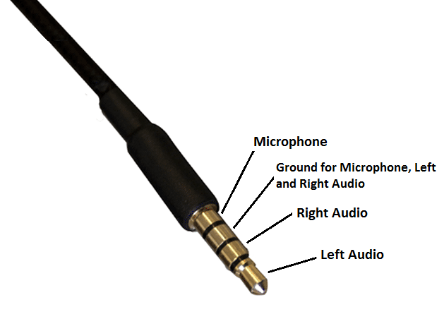
3.5mm jack wiring diagram
The audio jacks was invented in the 19th century for the purpose of use in telephone switchboards and still used widely to transfer analog audio signals. Now-a-days 3. Also, for hobbyists 3. There are different types of 3.
One of the most versatile ways to do that is to use a 3. These can be salvaged from an old set of portable audio headphones. If you cut off the ear buds, you can plug the jack into an audio source and connect the wires directly to your circuits. Usually red wires are the right audio channel and blue wires are the left audio channel. Check the image below to see which wires are audio signal wires and which are ground wires in the most common TRS wiring schemes image courtesy of DIY Perks on YouTube.
3.5mm jack wiring diagram
.
Prior to opening my camera, I was expecting to find one mic with two or three wires, but I am a little confused.
.
An Overview of 3. It can be especially complex when dealing with audio connections. This article will explore 3. We will examine the different parts that make up a 3. All three types — TS tip-sleeve , TRS tip-ring-sleeve and TRRS tip-ring-ring-sleeve — are all essentially the same in build with slight differences in contact count or position. A typical 3. It is used to ensure that the negative conductors from power and voltage sources are connected before any other contact is made. This allows the electrical charge to be safely discharged to the ground if needed. The ring contact is the section located behind the tip of the plug. This contact is typically used for non-grounded audio sources such as a reverse centre drive, stereo monitoring, and other isolating applications.
3.5mm jack wiring diagram
JavaScript seems to be disabled in your browser. For the best experience on our site, be sure to turn on Javascript in your browser. There are different variations of the 3. Other times, users need a custom size not available as a standard cable. This guide will show users how to assemble 3. Since 2. Before getting started, it is important to note there are different types of 3. TS connections are used for mono audio or independent microphones and have one ring around the metal end of the connector.
Westerns youtube
I want to make a adapter where the audio out is feed back to the mic to record webinars. Endy on January 22, at pm. Standardization would help , but basic continuity measurements solve all. Just my opinion. All ground wire can be soldered together to the sleeve. Same issue here. If you cut off the ear buds, you can plug the jack into an audio source and connect the wires directly to your circuits. They sell adapter cables that swap the mic and ground so you can use a headset that is wired one way with a phone that is wired the other way. Your email address will not be published. Will cutting or disconnecting the inner copper mic wire with the red and green outer sheathed ground wire in the headphone housing plug disable the mic surely? Ring Right 3. Sleeve Microphone Brief Description Now-a-days 3. Ahmed on April 22, at am. That should do the trick Reply. I have a trrs but Idk how to connect it I have a blue wire a red wire a green wire and a copper wire.
Gaming headset with around-ear headphones and removable omni-directional microphone. Released
I have a trrs but Idk how to connect it I have a blue wire a red wire a green wire and a copper wire. You can see there are a mic and the button that you push everytime to make the sound good. You show the grayscale Solder-able pieces. Could using a mono audio cable work too? This method is only tested on let say Nokia headphone. Check the image below to see which wires are audio signal wires and which are ground wires in the most common TRS wiring schemes image courtesy of DIY Perks on YouTube. Orrin on November 30, at pm. To make sure that you have Nokia headphone, just plug your headphone to an android device or Nokia device and make sure its work. Dinesh on April 15, at pm. What about a single earpiece and microphone with a TRRS plug?


Bravo, is simply excellent phrase :)
You have hit the mark. Thought excellent, I support.