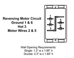
Rv slide out switch wiring diagram
Login or Sign Up. Logging in
This website uses Cookies. Click Accept to agree to our website's cookie use as described in our Privacy Policy. Click Preferences to customize your cookie settings. Good Sam Community. Help Sign In.
Rv slide out switch wiring diagram
Tracing slide power path, located fuse I was contacted by a person on a slide out power failure and possible location of fuse. As I didn't know I started looking. Not knowing where fuse was or if there was one realized could be issue. I first check all circuits in 12v fuse panel-nope slide is not tied to any fused panel circuit. A white wire feeds the switch-that doesn't help, all the white wires everywhere else in camper are ground wires. Wow, It feeds the switch, power to it is a blue wire. I think I added fuse when I added the Perko switch between battery and camper as main disconnect. There's an auto reset fuse on it!. Had no idea-less the board was even there. I relayed this information to the fella that contacted me. He did the same, removing end of box, retrieved circuit board. His though similar had a fuse instead of auto-reset breaker.
Magnetic switches are very commonly used for the sensor circuits stop point.
This is only a preview of the June issue of Silicon Chip. You can view 41 of the 96 pages in the full issue, including the advertisments. June - Silicon Chip Online. Items relevant to " Articles in this series: All about regenerative receivers May Restoring a 4-valve Howard receiver June
Login or Sign Up. Logging in Remember me. Log in. Forgot password or user name? Slide-Out Switch Wiring. Posts Latest Activity Photos. Page of 1. Filtered by:.
Rv slide out switch wiring diagram
When it comes to special features, y ou never know what RV makers will come up with. Some designs are for safety reasons while others just do not make any sense. Operating your slides may be a combination of those two categories and will have you scratching your heads in bewilderment.
Chat ave adult
There are several different feedhorn arrangements. With the drilling of the reflector metalwork complete, you can now pop rivet both reflector grille assemblies. The slide-out that was stuck open is also shown below. Another reader did write in about this some time ago but I cannot remember when or the exact outcome. When someonewallks within range up to 15m away the verandah Is Ill upfor a period of 5 seconds to 10 minutes, or more. Search instead for. Part F is half the dipole which is detailed in Fig. Then the husband said he could hear it faintly but his wife could not, and neither could I. Cutting out the aluminium dipole sections is one of the more tedious steps in making this antenna and this is where having access to a guillotine would be good. Posted September 27, We've had a few of these, but only on the chassis fitted to that model set".
.
Suits T and T Irons. Torx Bits T, The ONLY purpose I could see is if board sensed high load slide fully in or out and cut power to motor. However, this does not preclude the reception of SCPC audio services. It would indeed be a boost if the industry was to relaunch AM stereo and this time around, do it properly! Thanks for the great feedback! In fact, for every 20°K drop in noise temperature, there is a co rresponding 0. Log in. Lot easier doing this type of stuff at home When the dielectric insert is positioned on the righthand side of the probe, the feedhorn will intercept right hand circularly polarised RHCP signals.


0 thoughts on “Rv slide out switch wiring diagram”