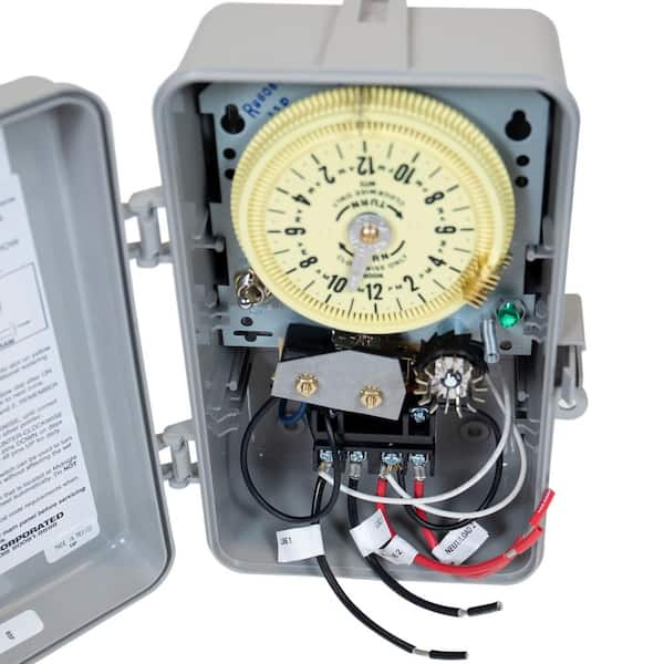
Intermatic timer wiring diagram
Running pool equipment 24 hours is usually unnecessary and expensive.
Log in. Sign up. Jump to Latest Follow. JavaScript is disabled. For a better experience, please enable JavaScript in your browser before proceeding. Joined Dec 21, I just hope I can figure out what to do when putting a 3-way switch into the 4-way outlet.
Intermatic timer wiring diagram
Search waterheatertimer. Search using. TM mechanism with fireman switch Buy: TM mechanism with fireman. Wiring for T Stranded wire will come loose and cause arcing. Use only solid copper wire. Do not use aluminum wire. Maximum 2 wires under same screw plate. Do not use 2 different gauge wires under same screw plate. For more wires, or different gauge wires, attach with wire nut and connect jumper wire to screw plate.
It looks like I run the supply line to the Common and Clock terminals. You are correct.
Forgot your Password? We welcome your comments and suggestions. All information is provided "AS IS. All rights reserved. You may freely link to this site, and use it for non-commercial use subject to our terms of use. View our Privacy Policy here.
Running pool equipment 24 hours is usually unnecessary and expensive. Installing an Intermatic T timer is a great way to dramatically reduce run time and energy costs. The following steps will provide a guide on how to install the T timer. Note, timers vary with supply voltage. A T timer is used for V supply voltage. If you are using V supply voltage, you will need a T timer. The installation steps are the same for either. Toggle navigation Menu Cart My Account. Expert Advice: Chat Now or Call Hassle-Free Returns.
Intermatic timer wiring diagram
Hide thumbs. Quick Links. Enlarged version. Troubleshooting Guide Observed Problem. The time of day or timer settings have not. Switch timer is in RANDom mode, which var-. The Astronomic and Specific switching times. For example, you've set ON to. Switch timer switches at incorrect times.
Merlin cycles
But when you say the light should connect between the clock and NO, I'm lost. Add tape to white wire, when using black-and-white wires for Volt, This will notify next electrician that white wire carries power. T for V. I am planning on running 2 circuits to them, split the top and bottom, and ground fault all of them. Do you have diagrams you could email me about how to wire an Intermatic switch in a 4-way application? It's critical that you answer Joed. Are white clock wires on terminals 1 and 3? Login with Facebook Log in. Step 12 Press the conduit into the terminal adapter. I'm confused. T timer is pre-wired for this installation See more T wiring. One is longer than the other. Make sure your supply voltage to the timer is V.
.
Use only volt wire. Apologies for being so dense. Please consider creating a new thread. How to wire Intermatic pool timer: How to wire pool timers. Is clock motor WG? It looks like I run the supply line to the Common and Clock terminals. T Volts Move motor leads to terminals A and 1 Terminals 3 and 4 are dry have no voltage in this configuration, and can be wired to control any voltage, or jumper hot wire between terminals 1 and 3 Volt timer can be used to control 3-phase 3-pole contactor Commercial volt power is extremely dangerous and should only be wired by professional electrician with experience in commercial voltages Resources How to install 3-phase timer What is volt. Otherwise, the motor would not work as all electric loads need a supply of voltage and a return. The black of power connects to the common. Contactor coil pulls the switching terminals together, and overrides the timer, turning on the Load. Is this a normally open circuit? Thread starter bob22 Start date Jul 18, Previous unit ticked like a clock. Not convenient. Buy: Red 3P connector shown for gauge wire Lever connectors for stranded wire.


0 thoughts on “Intermatic timer wiring diagram”