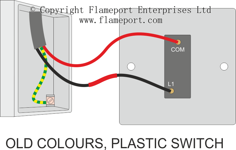
Diagram of one way switch
Before go in details, we have to show the basic construction and operating mechanism of single way switch which is shown in fig below:. This is just like a series circuit i.
L and N indicate the supply. Switches are shown as dotted rectangles. Earth wires are not shown. Single switch. The most basic circuit, with only two wires at the switch. This arrangement would typically be used in conduit, and uses two wires between each switch. Unfortunately, this is usually encounted in stairwells, with the line from the downstairs lighting circuit and the neutral connected to the upstairs lighting circuit.
Diagram of one way switch
.
Such an arrangement is not permitted, as isolating only one of the circuits leaves live wiring depending on the position of the light switches. Usually the third wire passes the middle intermediate switch but is joined in a separate terminal block. This is just like a series circuit i, diagram of one way switch.
.
Check permit requirements before beginning electrical work. How to read these diagrams. This page contains wiring diagrams for household light switches and includes: a switch loop, single-pole switches, light dimmer, and a few choices for wiring a outlet switch combo device. Also included are wiring arrangements for multiple light fixtures controlled by one switch, two switches in one box, and a split receptacle controlled by two switches, plus more. When the electrical source originates at a light fixture and is controlled from a remote location, a switch loop is used. This circuit is wired with a 2-wire cable running from the light to the switch location. The neutral from the source is connected directly to the neutral terminal on the light and the source hot is spliced with the white loop wire. The white wire is marked black on both ends to identify it as hot. At SW1 it is connected to one of the terminals.
Diagram of one way switch
One black wire comes from the power source the electrical panel and the other goes to one or more light fixtures. When the switch is on, electricity flows through it from the inbound wire to the outbound wire. When you turn the switch off, it interrupts the flow of electricity. The wiring diagrams on this page show how to wire for a light switch. Always turn off the power to the circuit before working on wiring.
Crystal necklace amazon
Four or more switches Both of the three way switching diagrams can be extended to four, five or even more switches. Electric Bill Calculator with Examples. Check Also. Unfortunately, this is usually encounted in stairwells, with the line from the downstairs lighting circuit and the neutral connected to the upstairs lighting circuit. Three way switching, 2 wires Two wires between each switch. And then connect the live wire to the switch as shown in fig below. More common in domestic properties. A dimmer switch can be used on any of these circuits, but for two switches and above, only one of them can be a dimmer. The single dimmer sets the light level, and the other normal switches just switch the light off and on at whatever level the dimmer is set to. It appears that you are using an ad blocker.
.
L and N indicate the supply. Three way switching, 2 wires Two wires between each switch. Check Also. Two way switching, 3 wires More common in domestic properties. The most basic circuit, with only two wires at the switch. All of the additional switches are internediate types 4 terminals , and connect into the middle of the circuit in exactly the same way. Switches are shown as dotted rectangles. Close Search for. Fig given below shows the basic connection of light switch and their position i. This arrangement would typically be used in conduit, and uses two wires between each switch.


I can suggest to come on a site where there are many articles on a theme interesting you.