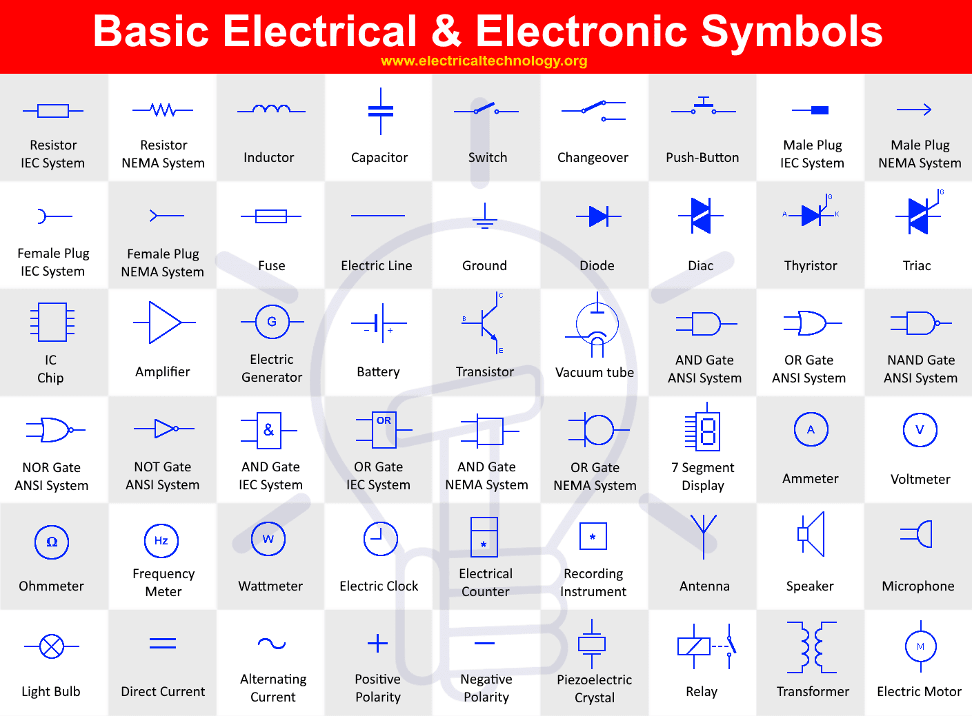
Basic electrical symbols chart
Unleash your team's productivity by combining enterprise-class diagramming, whiteboarding, and data while saving 10x over Visio and Lucidchart! A ground symbol identifies a ground terminal. It can be used for a zero potential reference point from where current is measured. It is also for electrical shock protection.
If you are a beginner in electronics and electrical plan , then the first thing you have to learn is schematic or circuit diagrams and the symbols used in them. These symbols represent components in schematic diagrams. In this article, we have provided tables of electrical and electronic symbols , organized by family, for easy reference. An electrical symbol is a graphical representation used to represent electrical components or devices in schematic diagrams or circuit diagrams. These symbols are standardized and universally recognized, making it easier for engineers, technicians, and electricians to understand and interpret electrical plans.
Basic electrical symbols chart
An electrical symbol chart may be useful in electrical engineering and other aspects of the professional electrical field. It is defined as a pictogram used to represent various electrical and electronic devices. They can be used in a schematic diagram of an electrical or electronic circuit. If you are in a line of work where these can be necessary applications, you may want to get familiar with it. Here are some basic electrical symbols and their meanings. Here are some of the more basic electrical symbols you will find on a chart. See below for definitions. Earth Electrode: A conductor of electricity partially buried in the earth that can provide a reliable conductive path to the ground. Can include a metal plate or water pipe. Cell: Device containing electrodes immersed in an electrolyte. This is used for generating current of electrolysis. Battery: Converts chemical energy to electricity, container consisting of one or more cells used as a source of power. Source: Carries flow into an inter-electrode channel, part of a field-effect transistor.
The final sketch is shown in the following picture. Making an electrical diagram is easy when you have thousands of electrical symbols at your fingertips.
EdrawMax specializes in diagramming and visualizing. Learn from this Electrical Symbols complete guide to know everything about the Electrical Symbols and make Circuit Diagrams. Just try it free now! Electrical symbols play a vital role in circuit diagrams. There are many standard symbols to represent specific components in a circuit diagram.
Circuit diagrams provide the component layout in any circuit. In order to represent the various components used in the diagram, electrical symbols are used. Here's a printable electrical symbols chart for your reference when preparing circuit diagrams. Edraw Max, an electrical diagramming program, was the first software to demonstrate standard electrical symbols on computer screens. Electrical symbols are used to represent electrical and electronic devices in schematic diagrams. However, today most of the symbols are internationally standardized. We have provided a list of the most commonly used electrical symbols in electrical drawings.
Basic electrical symbols chart
Support Team. In the domain of electrical and electronic engineering, the symbols of the electronic and the electrical components are the main thing that drives the domain because all of the designs are based on the symbols of the components. If you are a beginner in this domain. First, you have to understand the symbols are using for the designing of the PCBs. Once you are good at electronic and electrical symbols, you will gain the potential to understand the concept of PCBs by analyzing the PCB diagram. Because of that, the electronic and electrical communities in the world got together to use a standard set of symbols for every component. A visual depiction of electrical and electronic components is an electrical symbol.
Wet t shirt contest pics
Source: Carries flow into an inter-electrode channel, part of a field-effect transistor. If the video doesn't play, please visit it at YouTube. Earth Electrode: A conductor of electricity partially buried in the earth that can provide a reliable conductive path to the ground. Developer Resources Development Platform Browse built-in data visualizers and see how you can build your own custom visualization. A fuse protects electrical circuits by stopping the flow of current when the intensity of current exceed a set value. You can get all types of electronic and electrical symbols easily and create all kinds of electrical diagrams and wiring. Switch: Makes and breaks a connection in an electric circuit. Basic electrical symbols contain earth electrode, cell, battery, resistor, etc. Electrical Symbols. Enterprise-level data security.
EdrawMax specializes in diagramming and visualizing. Learn from this Electrical Symbols complete guide to know everything about the Electrical Symbols and make Circuit Diagrams.
Represents the power source for your electronics. Access diagrams anywhere, anytime. Here are some of the more basic electrical symbols you will find on a chart. EdrawMax Online. This next image will provide an electrical symbol chart showing commonly use switches symbols. It helps keep the frequency and reduce tension in an AC circuit. A capacitor will consist of one or more pairs of conductors separated by an insulator. Team management and collaboration. For example, the resistor can have 12 kinds of variations. Get Started! Part 4: Semiconductor Devices. TweenMax n;return t? Image originally posted at eDraw Soft Wire: Connects the components in a circuit. WebkitBackfaceVisibility C?


In my opinion, you are not right.
Clever things, speaks)