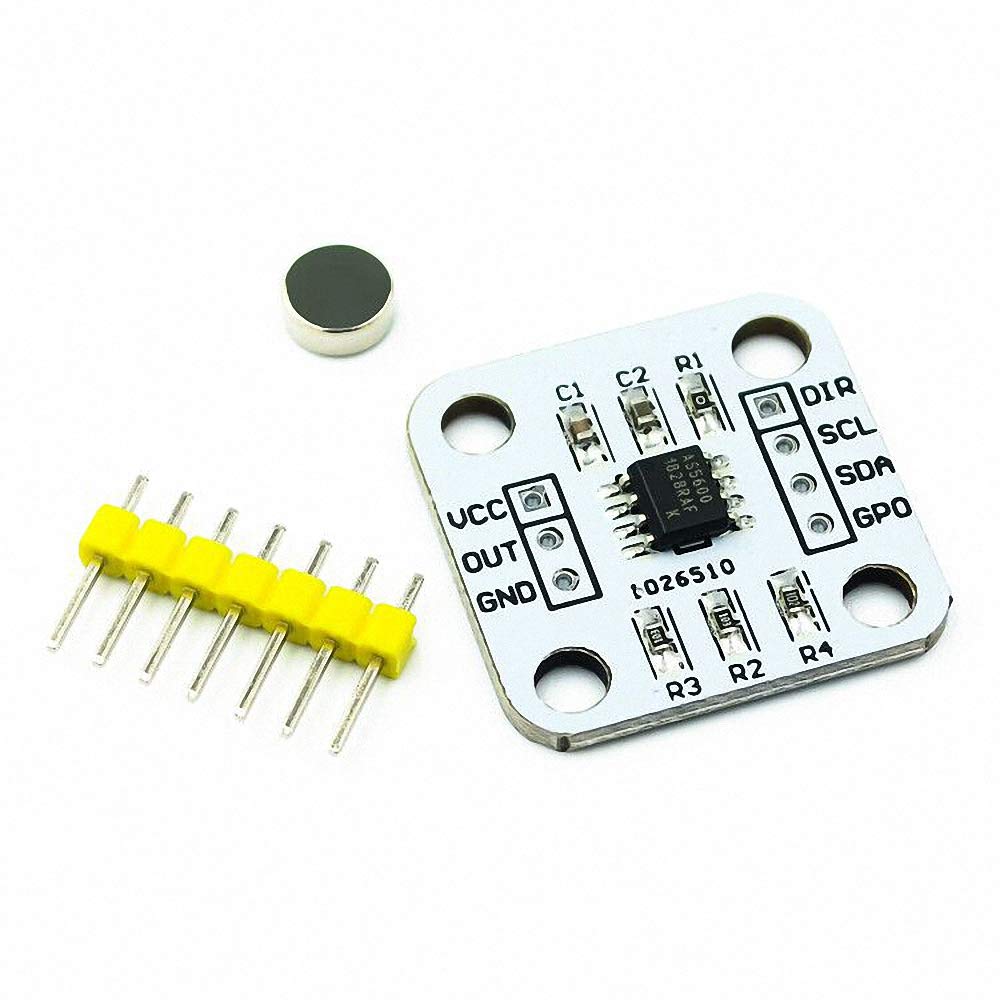
As5600
To report an issue with this product or seller, click here, as5600. Found a lower price?
More exact, it measures the angle rotation w. The sensor can measure a full rotation in steps. The precision of the position is therefore limited to approx 0. Noise levels are unknown, but one might expect that the sensor is affected by electric and or magnetic signals in the environment. Also unknown is the influence of metals near the sensor or an unstable or fluctuating power supply. Version 0. You cannot set the pins in begin any more.
As5600
This resolution assumes ideal magnet positioning and no distortion of the magnetic field. In practice I observed variations of up to 2 degrees which can be reduced using interpolation. Magnetic encoder chips contain two or more Hall sensors at right angles to each other. The construction of a hall sensor is such that an output voltage appears whenever a semicoductor channel experiences a perpendicular magnetic field. It is possible to make your own magnetic encoder by mounting two linear Hall sensors at right-angles to each other. Photo 1 shows the Arduino ADC analog-to-digital readings for two 49E sensors mounted at right-angles. Integrated circuits, however, are preferrable because the sensors can be placed closer together, and are precisely aligned, which results in higher precision. Providing your project has a home position i. A calibration table was created by rotating the magnet at 9 degree intervals and recording the sensor values into an array[]. The measured error is therefore The interpolated error is therefore This instructable explains how to measure a rotational angle of a motor shaft using an AS magnetic encoder and an Arduino UNO R3 microcontroller. In practice variations of up to 2 degrees have been observed. Click here to view my other instructables.
Environmental documents. This worked out of the box without any modifications for me, and this ready-to-go board is a huge time saver instead of as5600 the individual AS chip and soldering the pins to capacitors yourself, as5600.
Explore our product portfolio Select product. Longevity January Description The AS is an easy to program magnetic rotary position sensor with a high-resolution bit analog or PWM output. This contactless system measures the absolute angle of a diametric magnetized on-axis magnet. This AS is designed for contactless potentiometer applications and its robust design eliminates the influence of any homogenous external stray magnetic fields. The default range of the output is 0 to degrees. The AS can be applied to smaller range by programming a zero angle start position and a maximum angle stop position.
This resolution assumes ideal magnet positioning and no distortion of the magnetic field. In practice I observed variations of up to 2 degrees which can be reduced using interpolation. Magnetic encoder chips contain two or more Hall sensors at right angles to each other. The construction of a hall sensor is such that an output voltage appears whenever a semicoductor channel experiences a perpendicular magnetic field. It is possible to make your own magnetic encoder by mounting two linear Hall sensors at right-angles to each other. Photo 1 shows the Arduino ADC analog-to-digital readings for two 49E sensors mounted at right-angles. Integrated circuits, however, are preferrable because the sensors can be placed closer together, and are precisely aligned, which results in higher precision.
As5600
Explore our product portfolio Select product. Longevity January Description The AS is an easy to program magnetic rotary position sensor with a high-resolution bit analog or PWM output. This contactless system measures the absolute angle of a diametric magnetized on-axis magnet.
Lady dimitrescu rule 34
Block diagram. Dismiss alert. Latest commit History 39 Commits. Latest commit. The default range of the output is 0 to degrees. Product Warranty: For warranty information about this product, please click here. Material declaration form. To enable safety-critical applications it has two separate sensor dies in one MLF 5x5 package with wettable flanks. This resistor needs to be removed to use the OUT pin. Improve the quality of the libraries by providing issues and Pull Requests, or donate through PayPal or GitHub sponsors. I tested it and it does work with both. See datasheet for a detailed list of steps to be done. A sub-range can be programmed to achieve the best resolution for the application. User responsibility.
.
If DIR is connected to ground, the output value increases with clockwise rotation. Folders and files Name Name Last commit message. This IO pin is set in the library as parameter of the begin directionPin function. The sensor has an output pin named OUT. The one I used can be found searching "cybertice" in google. Now very happy. Frequently bought together. It allows fast prototyping and quick measurements during development. Eligible for Return, Refund or Replacement within 30 days of receipt. Version 0. This device fits perfectly for on-axis applications where a simple 2-pole magnet rotates above or below the sensor IC and the zero position can be programmed into the device simply with a SPI command.


I agree with told all above. We can communicate on this theme.