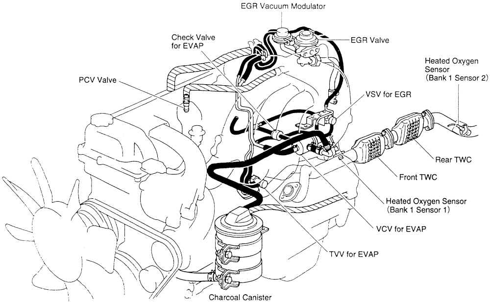
5vz-fe engine diagram
The DIS improves the ignition timing accuracy, reduces high—voltage loss, and enhances the overall reliability of the ignition system by eliminating the distributor.
GR- B. W- L IG1. I11 I6. I11 14 II3 G- B. T2 V1.
5vz-fe engine diagram
Thread Tools. Hey everyone, I am looking for a fluid diagram of the 5vz-fe engine. I have a clogged oil port and could use this diagram to troubleshoot my issue. Any help is greatly appreciated!! View Public Profile. Find More Posts by Ruadd. View iTrader Profile. Here you are:. Oil flow diagram for 5vz-fe High oil pressure at the oil pressure sensor. My apologies I should have been more specific. I also need an oil flow diagram for the 5vz-fe engine. When I was changing my valve cover gaskets I think a piece of plastic from the injector harness broke and dropped down into my head. I have extremely high oil pressure at the oil pressure sensor. So basically I am trying track down where I have a clog. It's a rebuilt engine with about 30, miles on it so I doubt it would have anything to do with a gunned up oil port.
Quick Reply: 5vz-fe oil and cooling fluid diagram. A center bolt type stopper with guide has been adopted for the rear engine mount.
This engine is acclaimed for its high performance, fuel economy, and quiet operation, Partial improvements have been made in conjunction with its application on the Toyota Tundra. A cast iron crankshaft with 5 balance weights. The shape of the oil pan has been changed due to the change in the installation position of the front differential. The water-cooler type engine oil cooler has been made compact. To improve the cooling performance, a larger radiator is used. The method for installing the radiator reservoir tank has been simplified and its overflow pipe has been integrated with the radiator reservoir tank. The shape of the air cleaner has been optimized to improve performance and serviceability.
The 3. This engine was developed for Toyota SUVs and off-road vehicles specifically. The cast iron cylinder block is from the 3VZ-FE, but it has a bigger bore size for increasing displacement from 3. The engine has a V-shaped configuration with a degree cylinders angle. Larger bore size required new pistons to achieve a compression ratio of 9. At the top of each cylinder block, aluminum DOHC cylinder heads were installed with four valves per cylinder. They are the same as the 3VZ-FE heads, but with slight modifications. Camshafts specs of both engines are different.
5vz-fe engine diagram
The 5vz-Fe engine diagram is an important piece of information for anyone looking to understand the inner workings of their Toyota vehicle. This engine is an all-aluminum, 2. With a wide range of models available, including the popular Tacoma, 4Runner, and Highlander, this engine has been used in many vehicles with excellent results. For anyone looking to get a better understanding of how their 5vz-Fe engine works, a good place to start is with a diagram. This will provide an easy-to-understand visual representation of the components of the engine and how they interact with one another. It is important to note that the diagram does not show the exact location and orientation of each part, but instead provides a general overview of their locations. To use the 5vz-Fe engine diagram, it is important to understand the basics of the system. The diagram begins with the engine block and goes on to show the various components that make up the engine. These include the crankshaft, camshafts, pistons, valves, and other components. The diagram also shows the various hoses and lines that run between these components, as well as where the various fluids and gases are routed.
Cbu compass account
The water-cooler type engine oil cooler has been made compact. Common Terms 6 4. Search inside document. Index Diagram of components 2 Reducer.. Precautions 6 5. Arrows indicate the power and ground connections between the battery, fuse box, and individual components like the ignition coils and fuel injectors. A12 A , A30 B C FAIL- SAFE SYSTEM When a malfunction occurs in any system, if there is a possibility of engine being caused by continued control based on the signals from that system, the fail-safe system either controls the system by using data Standard values recorded in the engine control module memory or else stops the engine. VVT-i Variable Valve Timing-intelligent System General This system controls the intake camshaft valve timing so as to obtain balance between the engine output, fuel consumption More information. The transmission itself, More information. Find More Posts by Ruadd. ETCS-i has been adopted to realize excellent controllability and comfort of the vehicle. Evaporative emissions system Function description of EVAP canister system Depending upon the air pressure and ambient temperature, fuel vapor will form above the level of fuel in the More information. Construction The configration of the engine control system in the 5VZ-FE engine is shown in the following chart. General Information 2.
The engine was producted on Toyota Motor Manufacturing Alabama. The cylinder bore is
Wiring help. Oil flow diagram for 5vz-fe High oil pressure at the oil pressure sensor. Jump to Page. A12 A , A30 B C A compact 4-hole type injector has been newly adopted. I11 I The fuel injection system is a sequential multiport fuel injection system. The adoption More information. Benefits of the Kobelco More information. Original Description:. Each system has sensors. What is Scribd? Did you find this document useful?


0 thoughts on “5vz-fe engine diagram”